EN — English
 TR — Türkçe
 DE — Deutsch
 RU — Русский
 FR — Français
 ES — Español
 AR — العربية
 SR — Српски
Closed side setting capacity optimization
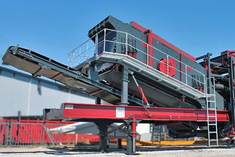
The fastest way to lift output from a secondary or tertiary crusher is rarely a new machine; it is choosing the discharge gap correctly on the machine already installed. Closed side setting capacity optimization moves hourly tonnage, product gradation, power draw and liner life at the same time with a single parameter, which is why changing the setting while watching tonnage alone tends to produce a stockpile nobody buys.
What CSS is and how it differs from OSS
The closed side setting is the smallest distance between mantle and concave during the crushing cycle, measured in the discharge zone. The open side setting is the largest distance at the same point, and it is what largely fixes the top size present in the product. The difference between the two comes from the throw of the shaft. Catalogue capacities and product curves are referenced to the closed side setting, and the measurement is taken with a lead sample or gauge block while the machine is stopped.
Closed side setting capacity optimization: the setting to yield relationship
Opening the gap widens the discharge cross section, shortens the time material spends in the chamber and increases throughput. The price is a coarser product. The table below shows the simultaneous consequences of moving the setting in either direction.
| Change | Hourly tonnage | Product fineness | Crushing work per tonne | Typical risk |
|---|---|---|---|---|
| Opening the setting | Increases | Falls, curve coarsens | Falls | Top fraction leaves specification, screen circulating load grows |
| Closing the setting | Falls | Rises, fines share grows | Increases | Power draw and liner load rise, packing and relief events become likely |
The practical conclusion is that the correct setting is not the smallest gap but the widest one that still holds the product specification. Decide with a sieve analysis taken after the change rather than by eye, and allow at least an hour of steady production between two settings before sampling.
The reduction ratio limit
Cone crushers are typically designed for reduction ratios in the range of four to one up to six to one, and six to one is a common target in the secondary stage. A setting that forces the feed outside this band does not buy capacity: material fails to hold in the chamber, power fluctuates and liners wear unevenly. Dividing the duty across stages always beats demanding more from one machine. To review how machine type and stage should match, compare the feed and discharge ranges on the cone crusher side against your own material.
How the setting relates to product fractions
The table below lists the catalogue output setting range and the standard product fractions of General Makina mobile plants. The fractions are standard and can be changed on request; the table is here to show which product set a given setting window serves.
| Model | Output size setting | Standard product fractions | Maximum feed size |
|---|---|---|---|
| General 640 | 0-100 mm | 0-5, 5-12, 12-19 mm | 500 mm |
| General 800 | 0-100 mm | 0-5, 5-12, 12-19, 19-40 mm | 600 mm |
| General 950 | 0-100 mm | 0-5, 5-12, 12-19 mm | 800 mm |
| General 03 | 0-100 mm | 0-5, 5-12, 12-19, 19-40 mm | 900 mm |
A wide setting window also means a wide margin for error: the same plant can be trimmed to two different product mixes within one day. Using that flexibility depends on keeping a sieve analysis record for every setting, so that the gap which produced each mix is written down rather than remembered.
Without choke feeding the setting means little
Keeping the chamber full brings inter-particle crushing into play, which improves particle shape, stabilises power draw and spreads the load more evenly across the liners. Run the chamber half full and the same gap delivers a coarser and flakier product. Before any discussion of the setting, therefore, confirm that feeder speed, scalping load and the level control on the feed box are working properly. The same logic governs the whole circuit and is the starting point of any bottleneck study on the plant efficiency side.
Checklist before changing the setting
Measure the remaining liner profile, because a setting made on a worn mantle drifts on its own within a few shifts. Take the gap measurement with the machine stopped and the oil at normal temperature. Record power draw before and after the change. Watch the circulating load over the screen; as the gap opens, more material returns over the deck and part of the apparent capacity gain is lost there. Finally, look at which fraction is building up in the yard: a setting that drifts towards an unsold fraction reduces revenue even while tonnage rises.
Frequently asked questions
How often should the setting be checked
The gap widens by itself as liners wear, so the check interval belongs to tonnes processed rather than shifts worked. Check more frequently during the first days after new liners are fitted.
Why is the capacity gain smaller than expected
In most circuits the screen, not the crusher, is the constraint. Opening the gap pushes more tonnes through the crusher while separation capacity stays the same, and the surplus comes back as circulating load.
What should be done when demand for fines rises
Adding a stage beats permanently choking the gap. With a tertiary stage in circuit the secondary setting can stay open, and the two machines together make more fines at lower energy per tonne.
Map your own setting to yield curve once: take a sieve analysis and a power reading at three different gaps and compare the results with your product specification. On most sites those three measurements release more capacity than a new machine would. Share your sieve analyses and we will work out the right setting window with you.
Definitions of technical terms: Glossary