EN — English
 TR — Türkçe
 DE — Deutsch
 RU — Русский
 FR — Français
 ES — Español
 AR — العربية
 SR — Српски

Crushing and screening plant flowsheet design, worked backwards from the product
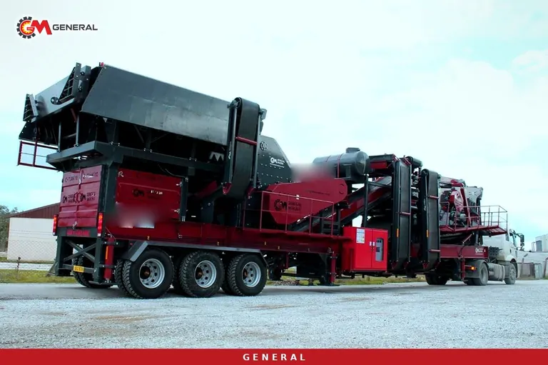
A flowsheet is a chain of decisions, not a list
Crushing and screening plant flowsheet design does not begin by listing machines to buy. The correct order runs the other way: define the product range to be sold, write down the monthly demand for each fraction, identify the fraction that is hardest to make and build the chain backwards from it. A design that starts by counting components can look complete on paper and still deliver either a surplus of fines or a permanent pile-up at one stage.
The logic of working backwards is straightforward. A plant exists to produce saleable material within defined size bands; crushers are the means to that end. The first number written down is therefore not crusher capacity but the upper and lower size limit of the target product.
Reduction ratio, the quantity that sets the stage count
Reduction ratio is feed size divided by product size, and in comparisons it is usually calculated from the sizes at which eighty percent of feed and product pass. Every crusher type has a band within which it works sensibly. Push past that band and capacity drops, wear accelerates and particle shape deteriorates.
| Crusher type | Typical ratio | Usual stage | Character |
|---|---|---|---|
| Jaw | 4:1 - 8:1 | Primary | Compression, suited to coarse and abrasive feed |
| Cone | 4:1 - 8:1 | Secondary and tertiary | Needs pre-sized feed, produces cubical aggregate |
| Horizontal shaft impactor | 10:1 - 15:1 | Primary and secondary | High reduction in one pass, more fines and wear cost |
| Vertical shaft impactor | 2:1 - 5:1 | Tertiary and quaternary | Shape correction and sand making rather than bulk reduction |
These figures are practical industry ranges rather than mechanical constants. Hardness, abrasiveness, moisture, feed gradation and machine settings decide where inside the band a given circuit actually operates.
Calculating how many stages are needed
Total reduction is the largest lump from the pit divided by the upper size of the target product. When that number will not fit inside one machine's band, the duty is split. Take a worked case: feed at 800 mm, product at 0-19 mm. Total reduction is roughly 42:1, and no single stage covers that efficiently.
| Stage | Machine | In | Out | Stage ratio |
|---|---|---|---|---|
| Scalping | Grizzly feeder | 0-800 mm | Fines removed, coarse to the crusher | - |
| Primary | Jaw | 800 mm | About 130 mm | About 6:1 |
| Secondary | Cone or impactor | 130 mm | About 40 mm | About 3:1 |
| Tertiary | Cone or vertical shaft | 40 mm | 0-19 mm | About 2:1 |
Once the chain exists, the check is whether every stage sits inside its own band. Loading one stage at 10:1 while another idles at 1.5:1 produces the same total reduction and an unbalanced plant: the loaded stage becomes the bottleneck and the idle one becomes dormant capital.
Closed circuit or open circuit
In open circuit material passes the crusher once and is screened; anything still oversize stays in the product stream. In closed circuit the screen oversize returns to the same crusher. Closing the circuit sharpens the upper size limit and becomes unavoidable when the specification tolerance is tight. The cost is circulating load: the tonnage the crusher actually sees exceeds the fresh feed, and a selection made without allowing for that starts out undersized.
The size of the circulating load depends directly on screen efficiency, which expresses how much of the undersize present in the feed actually passes through the deck. As efficiency falls, more material returns, the crusher carries load it should not carry, and capacity disappears invisibly.
Treating screen area as part of the flowsheet
A common mistake is to treat screens as an accessory added once the crushers are chosen. If screen area is short, no combination of crushers will deliver the target product. Sizing the decks requires feed rate, bed depth, undersize proportion, moisture and aperture shape together. Blinding in wet material with a high fines content can make catalogue capacity meaningless on site.
Fixed or mobile: a decision that reshapes the flowsheet
The same flowsheet is realised as one continuous line in a stationary plant and as separate units feeding each other in a mobile arrangement. Mobile setups offer relocation and quick commissioning; stationary plants allow longer conveyor runs, larger stockpile areas and usually lower energy per tonne. The choice follows reserve life, relocation frequency and the width of the product range. That comparison is examined in detail in the guide on mobile, tracked and fixed plant selection.
A checklist for validating the scheme
Six questions close the design. Does every stage work inside its reduction band? Was circulating load allowed for when the crushers were selected? Is screen area adequate for the fraction in highest demand? Do surge capacities absorb a short stop at one stage without propagating it? Is the surplus fines fraction attached to a saleable product? And finally, was the feed gradation from the pit actually measured? The pit-side extensions of these questions are covered in the mining engineering articles.
Common questions
Are three stages always necessary?
No. Where the product top size is coarse, two stages may be enough. Total reduction decides the count, not habit.
Does an impactor reduce the number of stages?
It can, since it delivers more reduction per pass. The return is more fines and higher wear part consumption, a trade that usually loses in hard abrasive rock.
Does every plant need a closed circuit?
Only where the specification demands a tight top size. For wide-tolerance road material, open circuit is often sufficient.
How is surplus fines managed?
Either it is sold as a product or its generation is reduced. Unnecessary extra stages and over-reliance on impactors are the two usual causes of an inflated fines fraction.
Definitions of technical terms: Glossary