EN — English
 TR — Türkçe
 DE — Deutsch
 RU — Русский
 FR — Français
 ES — Español
 AR — العربية
 SR — Српски
Crusher emergency stop pull cord system
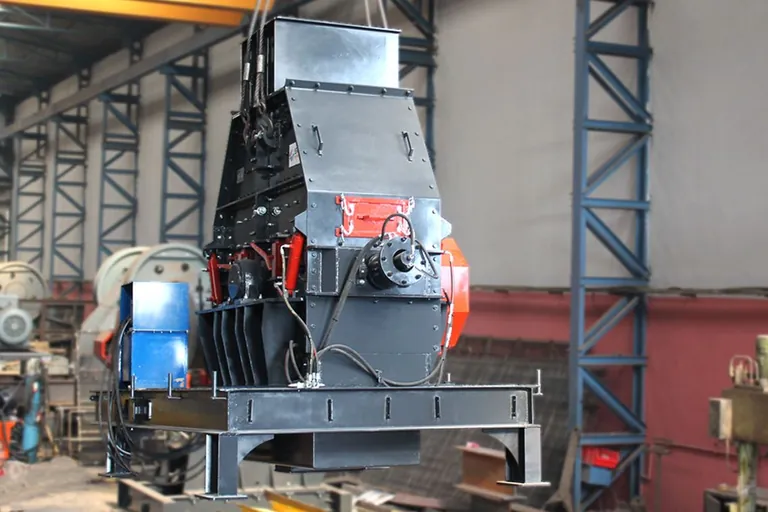
In a crushing plant the hazard never stays inside one machine. Feeder, crusher, screen and conveyors form a chain in which every unit feeds the next. A crusher emergency stop pull cord system exists to break that chain with a single movement: pulling the rope anywhere along the conveyor stops the group it belongs to. Whether it actually works depends less on owning the hardware than on where it is installed, how it resets and how often it is tested.
An emergency stop does not replace guarding
The emergency stop function is defined as a complementary protective measure. It is a last resort for averting or reducing a hazard that already exists, and it does not substitute for fixed guards, interlocked access doors or barriers under the belt line. In exchange, the function takes priority over every other command and operating mode: whatever the remote control, the automation recipe or a local start button asks for, the stop wins.
What a pull cord switch actually does
A pull cord switch is an emergency stop device triggered by pulling a steel rope tensioned along the conveyor. Once triggered it latches mechanically and stays latched until somebody resets it by hand; positive opening of the contact is the feature that guarantees the circuit breaks even if a contact has welded. In a properly engineered installation the stop is also triggered when the rope goes slack or breaks, because a broken rope is a safety line that is believed to work and no longer does anything at all.
Where a crusher emergency stop pull cord system has to reach
There is only one placement criterion: the function must be reachable from every point of the hazardous area. In practice that means the rope follows the walkway, and where walkways exist on both sides of the conveyor a rope is required on both sides. The maximum rope length a single switch can carry varies between devices and is read only from the manufacturer's manual, which also gives the spacing of the support eyes that keep the rope from sagging. On long runs temperature swings change rope length, so the tensioner indicator is set during installation and rechecked when the season turns.
Points away from the conveyor deserve the same attention: the crusher platform, the walkway around the screen, the control cabin entrance and the side of the feeder hopper. Mushroom-head devices cover those positions, and they belong to the same chain as the ropes.
Reset logic: stopping is easy, restarting safely is not
The rule is unambiguous. Resetting the device does not restart the machine. Unlatching only removes the stop command; running again requires a separate, deliberate start command. On site that means nobody can bring the plant back up before the person who pulled the rope has explained what happened. The device also has to be recognisable: the actuator is red, the background behind it is yellow, and neither surface gets a sticker or a handwritten label afterwards.
A second rule applies during the reset. Nobody resets a chain without knowing which point triggered it. If the panel does not indicate the activated location, fault-finding on a long line takes longer than the stoppage itself.
How the circuit is built
The chain is hardwired with the devices in series and executed through safety relays or a controller rated for the safety function. Leaving the stop decision to standard PLC software alone is not acceptable; the PLC at most reports which point raised the event. Cascaded stopping belongs to the same chain: when a belt stops, whatever feeds it must stop too, otherwise the stop is safe but buries the transfer point in material. How those interlocks are parameterised is settled on the automation and control system side.
| Check point | Method | Frequency | Acceptance |
|---|---|---|---|
| Every pull cord switch | Pull the rope in both directions | One point per line each shift, all points weekly | Switch latches mechanically and the drive stops |
| Rope tension | Visual check of the tensioner indicator | Weekly | Indicator inside the manufacturer's band, no rope sag |
| Broken rope simulation | Controlled release of the rope anchor | Annually and after every repair | Slack rope triggers the stop |
| Reset behaviour | Observation after unlatching | After every activation | Machine does not restart, separate start command required |
| Actuators and backgrounds | Visual inspection | Monthly | Red actuator on yellow background, not obscured by paint or dust |
| Records | Log the activation and the test | Every event | Date, location, cause and the person who reset it are written down |
Four defects seen again and again
First, a rope pulled along one side of the belt only, leaving the opposite walkway unprotected. Second, broken-rope detection that has never been tested. Third, no indication at the panel of which point tripped. Fourth, resetting from the control cabin rather than at the device: a restart performed without seeing the scene defeats the purpose of the whole chain.
Frequently asked questions
How many metres between switches?
There is no single universal distance. What governs is reachability from every point of the hazardous area, plus the maximum rope length stated in the device manual.
Should the stop brake the belt or let it coast?
That is an outcome of the risk assessment. On an inclined conveyor a coasting stop can allow runback, so the stopping method is fixed at design stage.
Are test records mandatory?
Without records there is no evidence the system works. A simple table carrying date, location, cause and the name of the person who reset it is enough.
The verification routine deserves as much documentation as the design itself; other articles under occupational safety deal with machine guarding and energy isolation practice.
Definitions of technical terms: Glossary